HEX-BIN-Trainer
Cook: mirwi
A project generated for our participation at 2wickl2014.
Also used at 32C3.
Basic idea
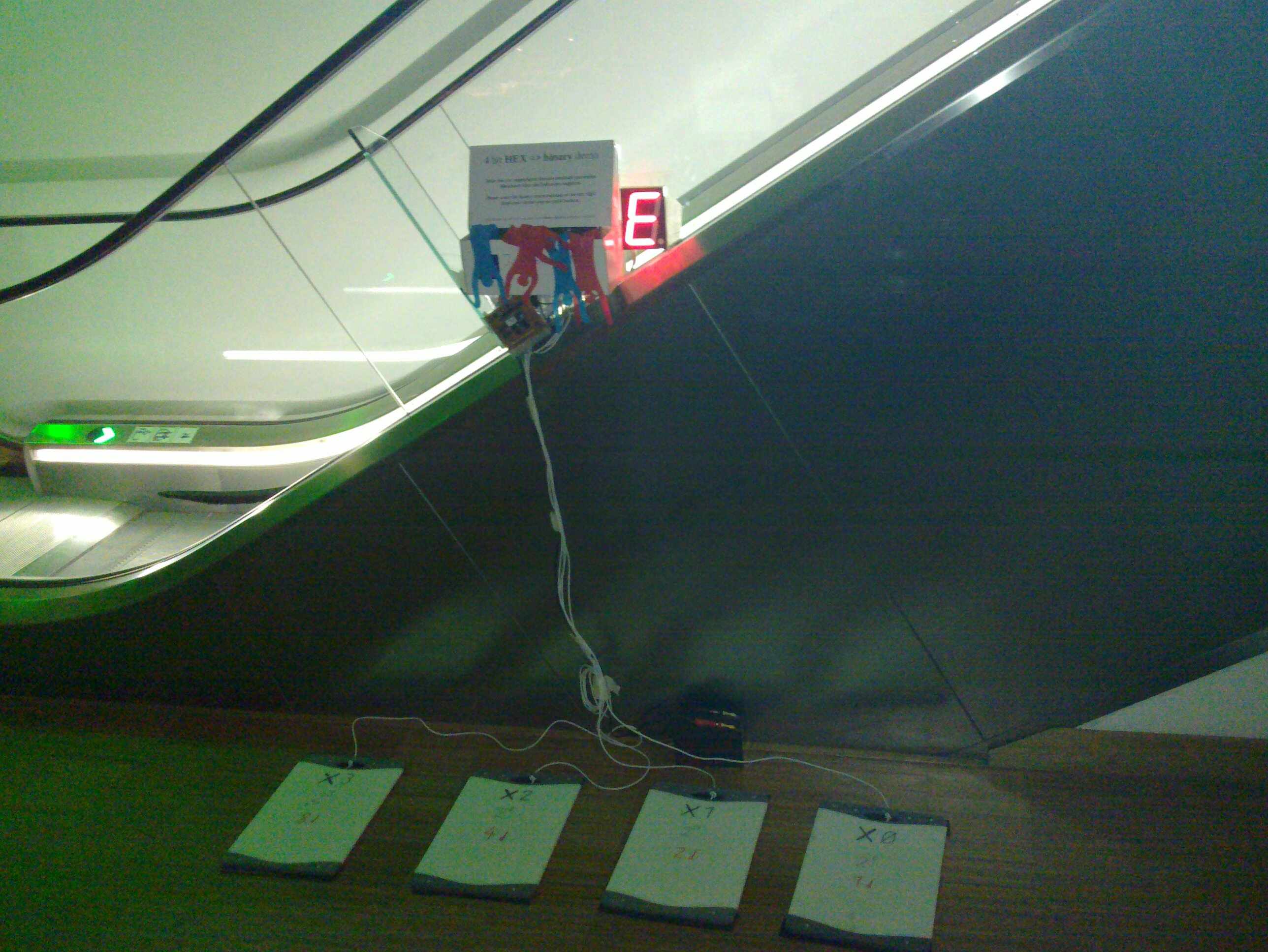
„Binary Kitchen teaches hexadecimal and binary number representations“. A random hexadecimal digit is shown by a 7-segment LED display. The users now have to enter the matching binary representation of that number. For the exhibition part at Zwickl this was done via big step-on push buttons. On matching bit pattern, a certain action (→Cheer box) was turned on for a short while. In parallel to that, a new random digit is generated.
Implementation
No brainer approach: uC - boring
The most obvious approach of these days would be to just hook the display and the input buttons up to a microcontroller and implement the limited functionality with a view lines of code. State of the art, but really boring.
So I took a second approach.
Nostalgic approach: TTL/CMOS graveyard
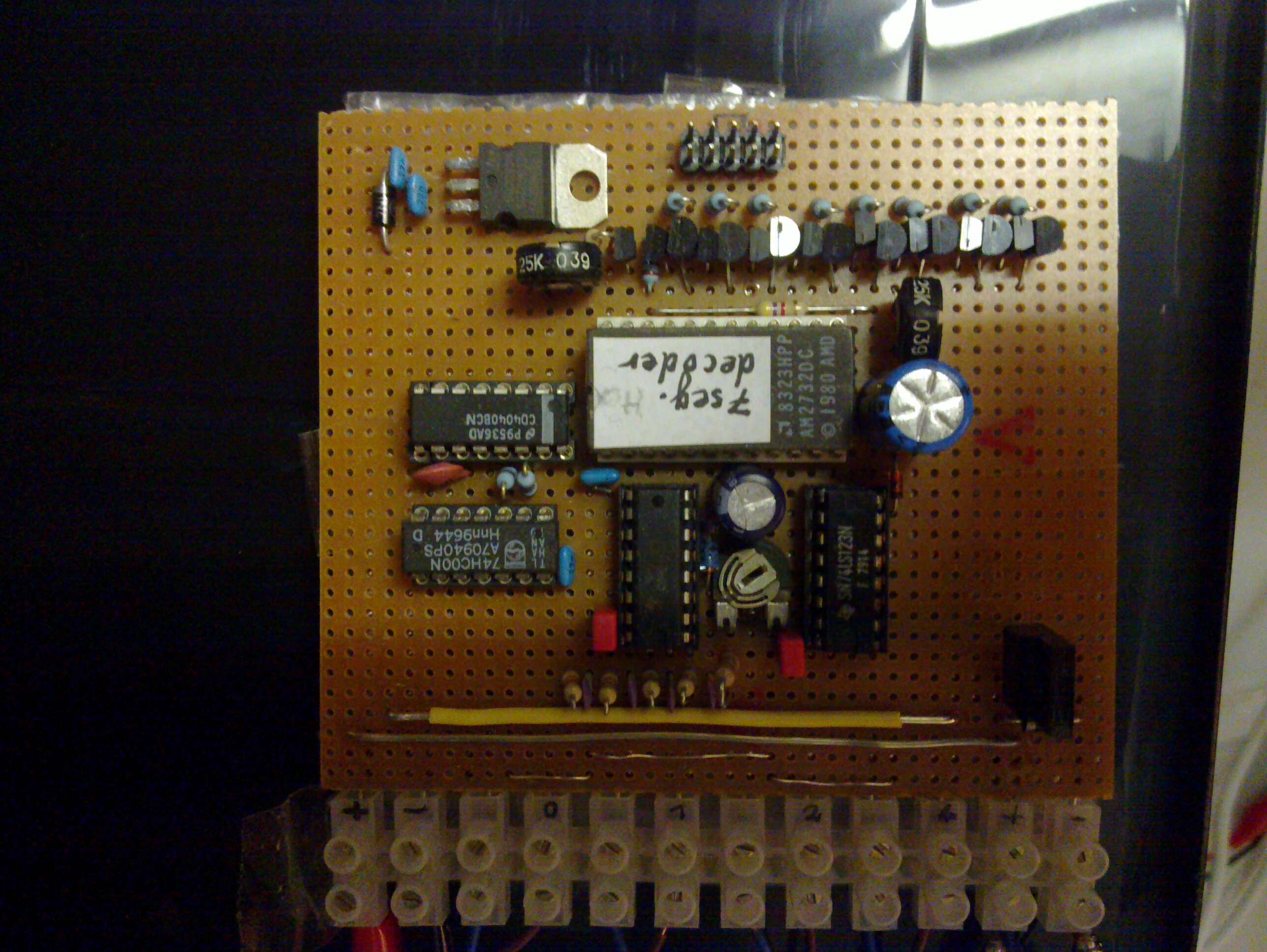
It is much more fun to build that circuit with discrete components. Well in reality it is all but discrete, as I'm using integrated logic ICs. But it almost feels like it in comparison to the uC approach. More over, it was nice to build something using this technique in a long time: Perforated circuit board with copper dots. Some major tracks are done with bare wire. Other signals are routed with insulated (enamelled) copper wire, also on the solder side.
Circuit description
Two of the four NAND gates of a 74HC00 are used to build a standard CMOS RC oscillator running at approximately 40 kHz. One of the NAND inputs is used to enable or inhibit the oscillator. Its output clock drives a 4040 11bit binary ripple counter. The lower four bit of the counter value are used as „random number“. It turned out, that it is really hard to get hold of a 7 segment display decoder/driver that covers the whole hexadecimal character set. As a replacement, the decoder table is programmed into an historic 2732 EEPROM, using only the first 16 byte of the memory space. Each of the eight data bits controls one of the display segments, including the decimal point (although not used till now). One BS170 MOSFET per segment is used to switch on the ground side connection. The used LED display is pretty large and, except for the decimal point, each segment consists of four LEDs in series. The common anode of the display is directly connected to the +12V supply voltage. In line with each segment is another bipolar transistor (of unknown type). Configured in a sort of current mirror circuit, they allow the brightness of all display segments to be controlled by a single, adjustable, reference current. In addition to the display decoder, the „4bit random number“ also feeds the reference inputs of a 4585 four bit comparator IC. The other set of inputs is connected to pull down resistors and to the input buttons, that provide +5V HIGH signals when pressed. The „inputs are equal“ signal of the comparator triggers one of the two monoflops in an 74HC123. The RC set time constant of it defines the turn on time of the „event output“. A more potent MOS-FET (IRF640) is used there to switch the ground side of an external load. At the same time the clock for the binary counter is re-enabled to get to the next „random“ number. While the counter is running, the displayed digit changes so rapidly, that all display segments appear to be turned on.
TODO: Draw a schematic. Really, I'm sorry, there is no drawn schematic for the whole circuit yet. Never has been. I build it with the data sheets of the ICs scattered around me…
Potential improvements: More bits from the counter value could be used for addressing the EPROM to select different „game modes“. The display decoder tables in memory could implement beside the current HEX→BIN also HEX→ NOT(BIN), BIN bit shifted, something with an even or uneven parity bit at some position … go let your fantasy go wild.
7 segment decoder table for the EPROM
Segment positions
| a | |||
| f | b | ||
| g | |||
| e | c | ||
| d | dp |
Truth table for the segment signals. Only the lower 4 bit of the address are used, the rest is assumed to be 0.
| Addr hex | D7 | D6 | D5 | D4 | D3 | D2 | D1 | D0 | Byte hex |
|---|---|---|---|---|---|---|---|---|---|
| a | b | c | d | e | f | g | dp | ||
| 0 | 1 | 1 | 1 | 1 | 1 | 1 | 0 | 0 | FC |
| 1 | 0 | 1 | 1 | 0 | 0 | 0 | 0 | 0 | 60 |
| 2 | 1 | 1 | 0 | 1 | 1 | 0 | 1 | 0 | DA |
| 3 | 1 | 1 | 1 | 1 | 0 | 0 | 1 | 0 | F2 |
| 4 | 0 | 1 | 1 | 0 | 0 | 1 | 1 | 0 | 66 |
| 5 | 1 | 0 | 1 | 1 | 0 | 1 | 1 | 0 | B6 |
| 6 | 1 | 0 | 1 | 1 | 1 | 1 | 1 | 0 | BE |
| 7 | 1 | 1 | 1 | 0 | 0 | 0 | 0 | 0 | E0 |
| 8 | 1 | 1 | 1 | 1 | 1 | 1 | 1 | 0 | FE |
| 9 | 1 | 1 | 1 | 1 | 0 | 1 | 1 | 0 | F6 |
| A | 1 | 1 | 1 | 0 | 1 | 1 | 1 | 0 | EE |
| B | 0 | 0 | 1 | 1 | 1 | 1 | 1 | 0 | 3E |
| C | 1 | 0 | 0 | 1 | 1 | 1 | 0 | 0 | 9C |
| D | 0 | 1 | 1 | 1 | 1 | 0 | 1 | 0 | 7A |
| E | 1 | 0 | 0 | 1 | 1 | 1 | 1 | 0 | 9E |
| F | 1 | 0 | 0 | 0 | 1 | 1 | 1 | 0 | 8E |
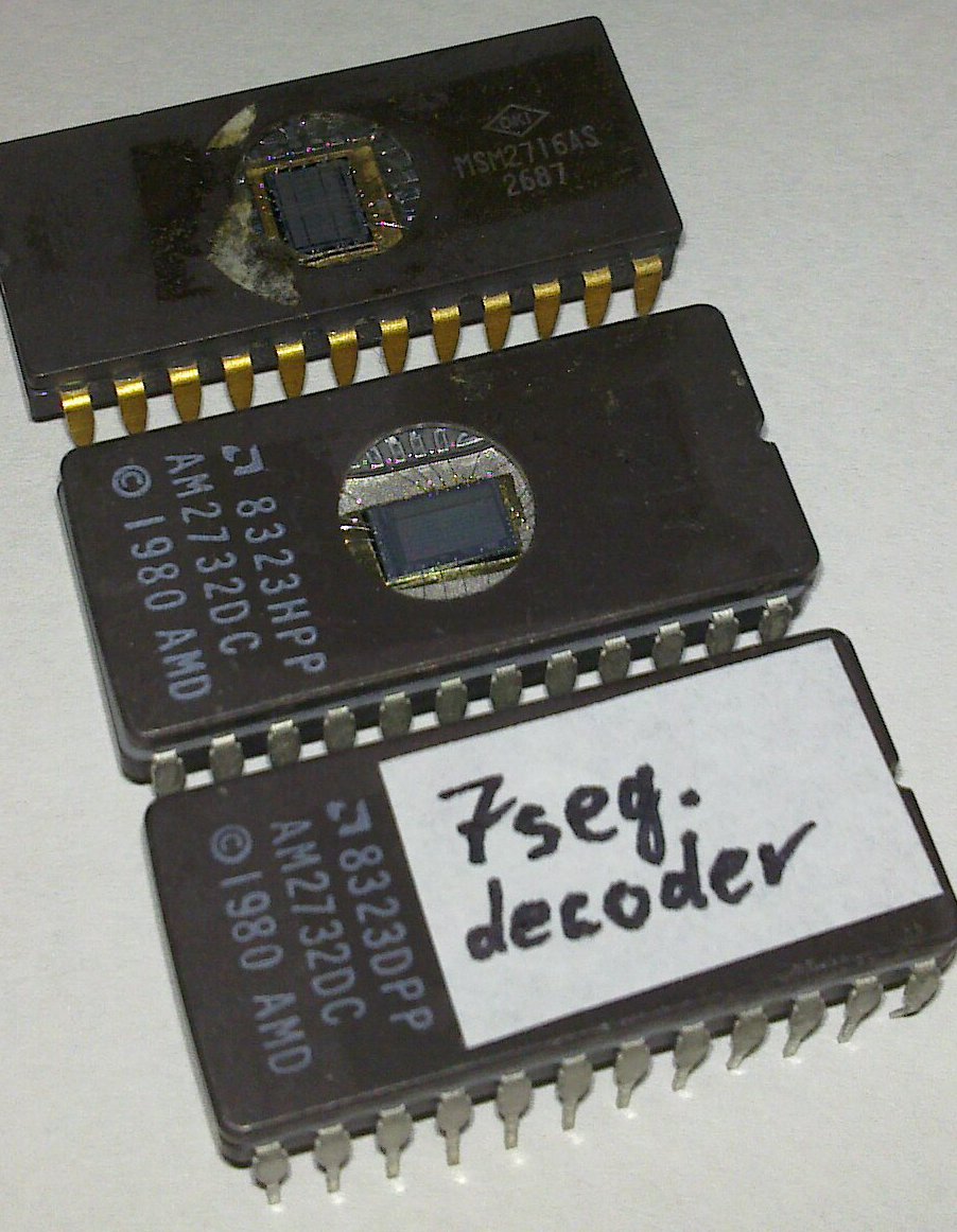
Initially there was a tiny mistake that made the F to be displayed as a P. It has been fixed in the table above and in the EPROM content.
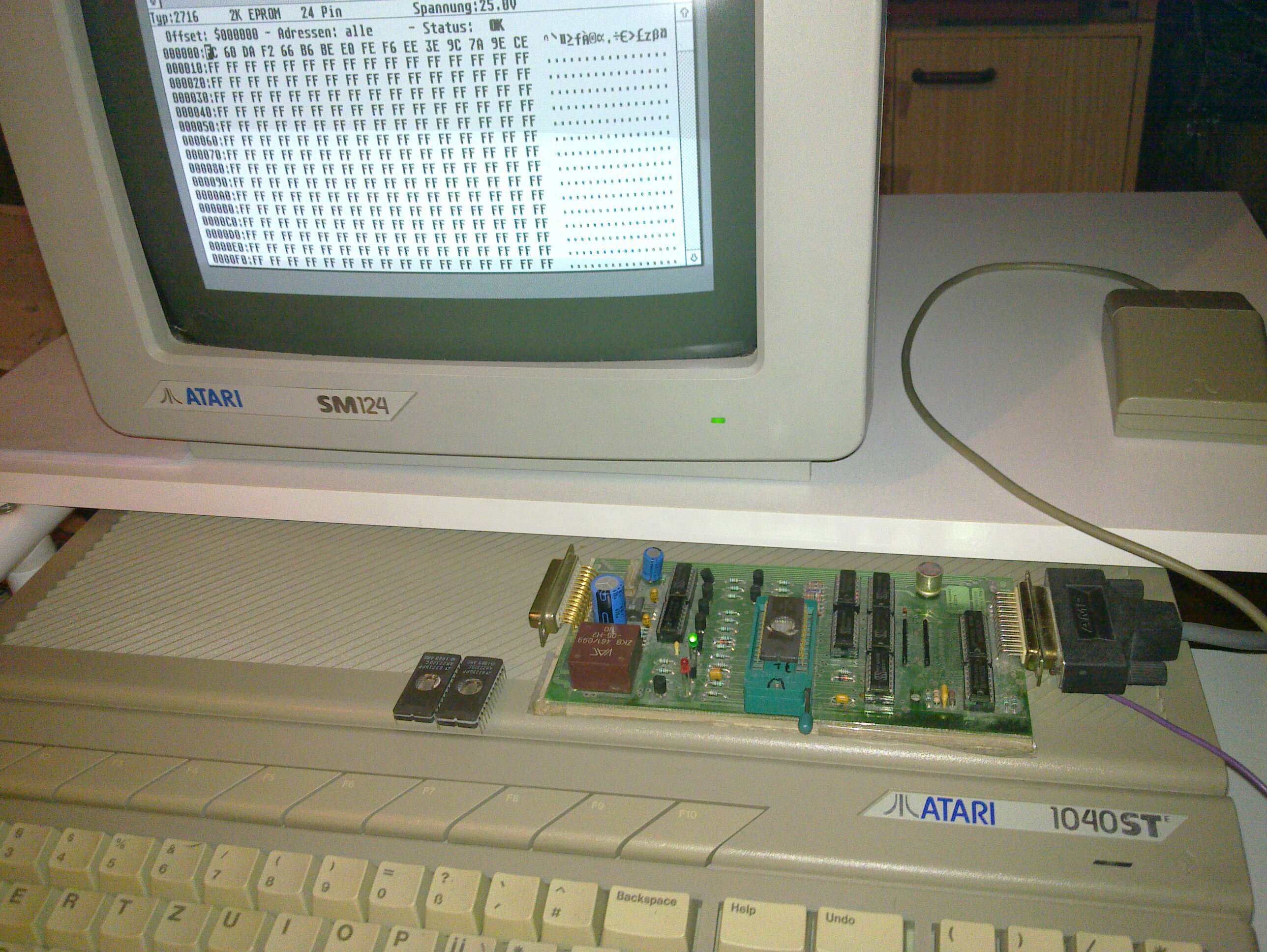
I still had three „small“, almost historic, EPROMs to feed the decoder data to. One was a 2716 (2kByte) and two 2732 holding a humongous 4kByte of capacity.
To stay within the theme, I had to use legacy hardware to program such old EPROMs. 
Circuit board
The whole set up at 32C3